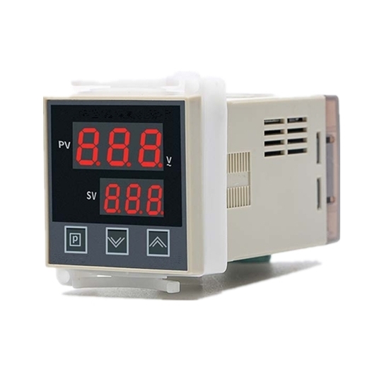
Features
Double-row LED digital display, real-time display of the current voltage.
High accuracy, strong shock resistance, good reliability, strong anti-interference ability, easy operation.
Adopt voltage negative feedback technology to stabilize AC voltage.
Specification
| Model | ZKG-2000-1 | ZKG-3000-2B | ZKG-300-3B | ZKG-2000A-2A | ZKG-2000A-3A | ZKD-6000-2A | ZKD-6000-3A |
| Control Output Type | Control SSR-DV Module | Control 1 pc of Two-Way controlled Silicon | Control 2 pc of Antiparallel SCR or 1 pc of SKKT | Control 1 pc of Two-Way controlled Silicon | Control 2 pc of Antiparallel SCR or 1 pc of SKKT | Control 1 pc of Two-Way controlled Silicon | Control 2 pc of Antiparallel SCR or 1 pc of SKKT |
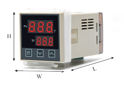
| Overall Dimension (L*W*H) | 48mm*48mm*90mm | 48mm*48mm*107mm | 48mm*48mm*75mm | 72mm*72mm*120mm | |||
| Opening Dimension (L*W) | 45mm*45mm | 45mm*45mm | 45mm*45mm | 67mm*67mm | |||
| Working Voltage | AC 220V 50Hz (Other voltages can customize) | ||||||
| Adjustment Range | 0-220VAC | ||||||
| Ambient Temperature | -5℃~40℃ | ||||||
| Relative Humidity | ≤85% in non corrosive gas occasion | ||||||
| Main Output Characteristic | Stabilized Voltage Output | ||||||
| Certification | CE | ||||||
| Installation Mode | Panel Type | ||||||
| Power Consumption | 3W | ||||||
Dimension Drawing Example
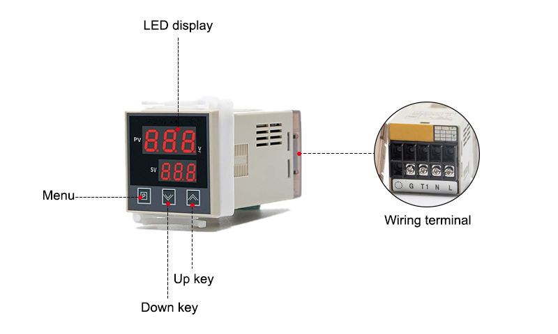
 Details
Usage and Adjustment
Switch the POWER to ON and the voltage regulator will work.
Adjust the plus key ∧ or minus key ∨ on panel to make the voltage on load displayed by PV reach the required value or change the set voltage value displayed on SV.
SCR voltage regulator uses negative voltage feedback. It is strictly forbidden to supply half-wave power to the load, so as to prevent the DC current on load from burning feedback transformer inside the instrument. In daily use, it is also necessary to prevent the unilateral conduction of the SCR.
Do not drive inductive loads such as induction furnaces and step-down transformers to prevent damage to the SCR.
If the SCR cannot be fully conducted or the output is severely jittered, it is caused by reverse connection of the trigger connection wires. Exchange the two trigger signal output wires to each other.
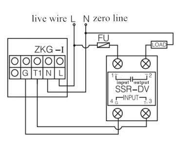
Wiring Diagram
| VRG-G1 | |
 | |
| VRG-G2B | VRG-G3B |
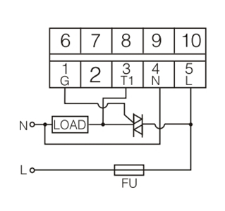 | 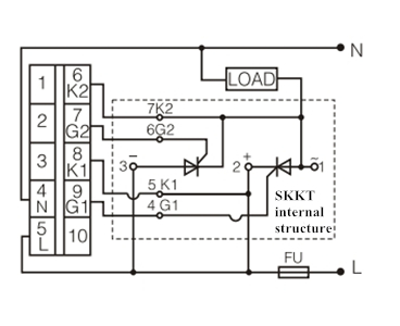 |
| VRG-G2A | VRG-G3A |
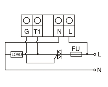 | 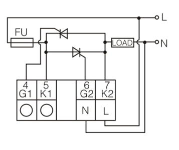 |
| VRG-D2A | VRG-D3A |
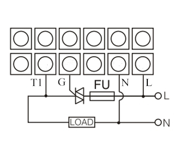 | 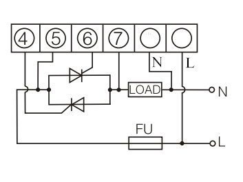 |
Installation Precautions
Input the output terminals G and T1 into power terminals L and N and the load LOAD. Working power must be in phase with the load power (that is, the same), otherwise SCR voltage regulator will be damaged.
Withstand voltage of the SCR must be more than 2.5 times the power supply voltage (for example: the use voltage is 220V, and the withstand voltage of SCR must not be lower than AC600V). SCR rated current must be more than 1.5 times the actual current used. SCR should be equipped with a sufficiently large radiator, and pay attention to good ventilation and heat dissipation to ensure that SCR temperature in any case does not exceed 70℃.
The fuse FU must be connected to input end of the phase wire (or SSR-DV input end) and must not be connected to other positions.
When installing thyristor radiator, full consideration should be given to preventing electric shock and short circuit with the thyristor electrodes.
If it needs to connect the ammeter, it must be connected in series with the T2 extreme side of the SCR.
For the instrument, each phase trigger signal line connected to the SCR should be as short as possible and be routed separately from other wires, so as not to interfere with each other and cause the SCR to trigger out of control.
